As I was researching what heater to put in our Fluval Spec V aquarium, I dutifully came across many grim reviews for various heaters that told of failures where the internal thermostat broke in the ‘on’ position, quickly baking (killing) everything in the tank. It seemed that I could try and spend more cash on a model that was more reliable, but the thing that stood out in my mind was that a failure could happen to any model of heater, no matter how much I spent, and the results would quickly destroy all my hard work.
One solution to this problem is to use a controller of some sort. There are many models that are specific to aquariums that usually offer great conveniences such as: timer control for multiple lights, water quality monitoring, heater control, chiller control, etc. I would love to play with all the bells and whistles on this type of product, but the price and complexity is beyond me at this point. As a compromise, I decided to go with a Do-It-Yourself solution and build my own aquarium temperature controller.
Note that this project is also often used for beer enthusiast for precise control of temperature in a device known as a Keezer or Kegerator. I don’t know anything about brewing, but the details for this build should exactly match your needs. Actually, the best writeup I found in my research was from this page at onemansbeer.com. Daniel did a fantastic job on his instructional write-up and his layout and wiring were the inspiration to my build and this page.
DIY Temperature Controller with STC-1000 (ITC-1000):
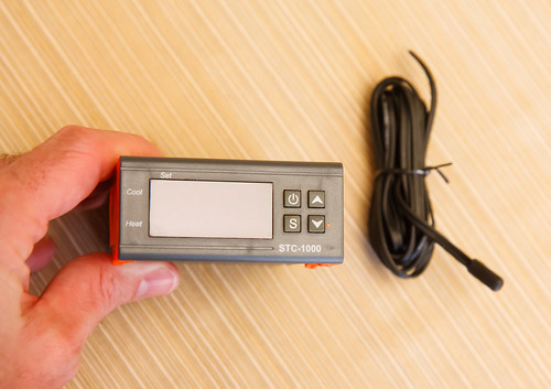
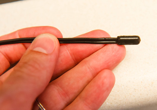
The core of the DIY temperature controller is the STC-1000. This device is a programmable controller and remote temperature sensor lead that serves as a relay to power a heating and/or cooling device.
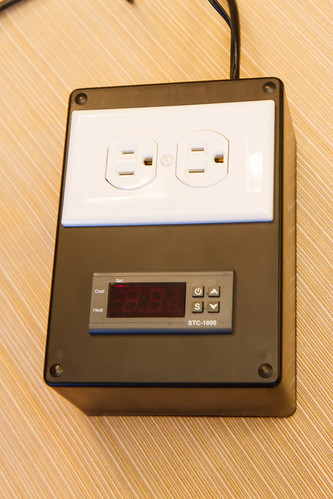
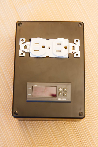
The DIY controller has the following layout: The controller is mounted in a project box to house the wires. Also mounted on the box is a two plug electrical outlet. Entering the box is a power cord and exiting the box is the temperature sensor on the end of a wire. Plugged into one of the outlets is your heater; plugged into the other outlet is a cooling device (fan, or freezer for our beer friends). The unit is programmed to maintain a certain temperature. If the temperature falls below the controller setpoint, power is supplied to the outlet that the heater is plugged into. If the temperature rises above the controller setpoint, power is supplied to the outlet that the fan or chiller is plugged into.
The beauty of this device is the expense – very accurate temperature control for around $30. The other draw to this build is peace of mind that no matter what happens at the heater, if the temperature rises too high (measured by the independent sensor) power will absolutely be shut off and the water will not be heated any more.
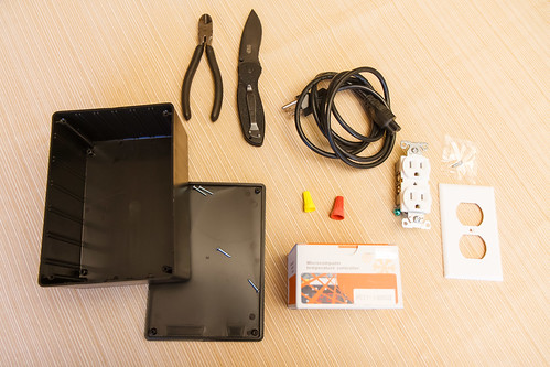
Materials Needed:
- STC-1000 Temperature Controller
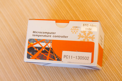
: This device can be readily found online and I would suggest eBay or Amazon as a source – I got mine from Amazon. There are a few things you want to add as keywords when searching. First, make sure to get the 110V version (not 220V AC or 12V DC) and second, include the word “Sensor” so you will also get the temperature probe. I have seen two versions of the probe; one plastic and one metal. I would suggest getting the plastic one as it will hold up better over time against corrosion, especially in a marine tank. (The link above will take you to the product as described.) EDIT: There is now an updated version of this temperature controller that allows the units to be switched from Celsius and Fahrenheit – it is the ITC-1000 Temperature Controller
. For the remainder of this page, references to STC-1000 and ITC-1000 are interchangeable.
- Project Box
: This is simply a plastic box that people (like us) use to mount electronic projects in. These are available at electronic shops – I got mine from Radio Shack. The box needs to be large enough to contain the STC-1000 (Including it’s depth) and enough surface area to mount both the face of the STC-1000 and an electrical outlet. The box I used is 7″ X 5″ X 3″.
- Electrical Outlet
: Nothing fancy – standard with two outlets.
- Wall Plate
: Used to cover the face of the outlet and make it look finished.
- Power Cord
: This is the power cord that will go to the box. As suggested by Daniel, I used an old computer power cord and that was plenty long. A simple extension cord could be used for this as well.
- Wire for Internal Connections: I used a few feet of my power cord (separated) to get sections of wire for the internal connections. This saved the cost of buying additional separate wire.
- Wire Cutter and Wire Strippers: Don’t be a hack like I am and use a pocket knife to strip wire.
- A Medium Size Wire Cap: The screw-on type to join some wires together.
- Dremel or Saw: to cut the openings in the project box for the STC-1000 and electrical outlet
- Drill and Small Drillbits: to drill holes in the project box for the power cord and the temperature sensor wire.
- Small Flathead Screwdriver: to tighten the wire terminal screws on the STC-1000.
Preparing the Project Box:
There are any number of ways to configure the project box but the basic premis is that there needs to be a space to surface mount the STC-1000 controller and the outlet (with wall plate). My controller was going in the bottom of a storage container and I wanted top access, so both openings were on the top. If you are observent in my blog you will see that I actually had to make another project box after I realized that the cords plugged into the top mount would not let the box close. I put the outlet on the side of the box in the new version.
The only other modifications that need to be made to the box are the holes for power cord entry and temperature probe exit.
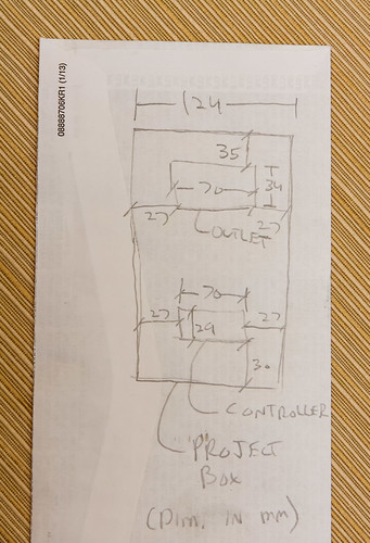
Step One: Mark cutouts on your box. I measured the dimensions of the controller and outlet and sketched a plan (dimensions in mm).
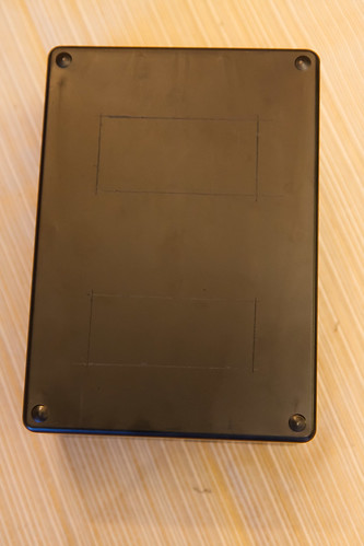
I then used a straight edge along those points and scratched marks into the surface using the point of a nail. This became the template for my cutouts.
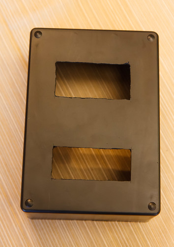
Step Two: Cutout holes in your box. I started by drilling a hole near an inside corner, then used a Dremel grinding bit from that point all the way around.
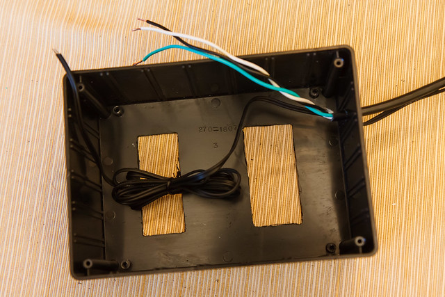
Step Three: Prepare the wires. First thing, prepare the power cord. I decided to have about 2′ of cord outside the box, so I worked backwards from there with an extra 10″ or so of wire inside. Strip off the casing for about 8″ to expose and separate the three wires within. I used the remainder of scrap power cord to make connection wire for inside. You need six pieces, about 8″ long or so. To make these, take your scrap cord, remove the outer casing to separate and get sections of white or black wire (you can use either or both so long as you can keep track of the connections). Strip a small piece of insulation from each end to expose bare wire.
Step Four: Drill the hole for the power cord. Start with a smaller bit than you need and work up until you have a hole that is just big enough for a tight fit. Go ahead the thread the power cord through the box wall to prepare for wiring. I wrapped multiple layers of electrical tape around the cord on the inside of the box as a ‘stop’ to keep it from being pulled out.
Step Five: Drill the hole for the temperature probe wire. I put this hole on the side closest to the aquarium. Go ahead and thread the temperature probe wire through the box wall.
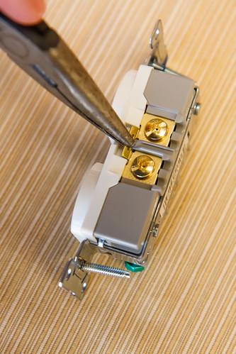
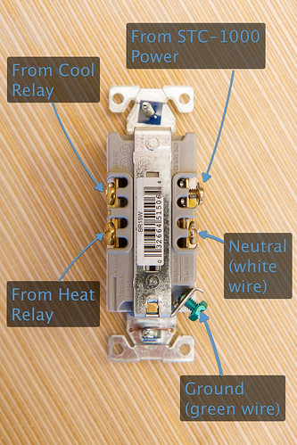
Step Six: Prepare the electrical outlet for dual control. There is one item of business to attend to before the electrical outlet is wired and installed. For this outlet to be able to separately feed a heater on one outlet and a fan / chiller on the other, you need to break the ‘hot’ tab. If you look at the outlet from the back, you will see a pair of silver screws on one side – this is the neutral side. On the other side are gold screws – this is the hot side. If you look a little closer at the metal below those two gold screws you will see a small piece that bridges between the two terminals. We need to break/remove this tab. Use a pair of small pliers to bend this back and fourth until it breaks off. It took a bit more effort than expected until it succumbed to fatigue. Make sure it is completely removed so there is no electrical connection between the two screw terminals.
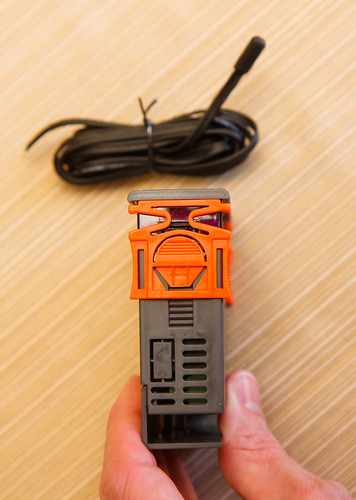
Step Seven: Mount the STC-1000 into the project box. The unit squeezes the project box wall between the outer face and an adjustable clamp (orange) on either side.
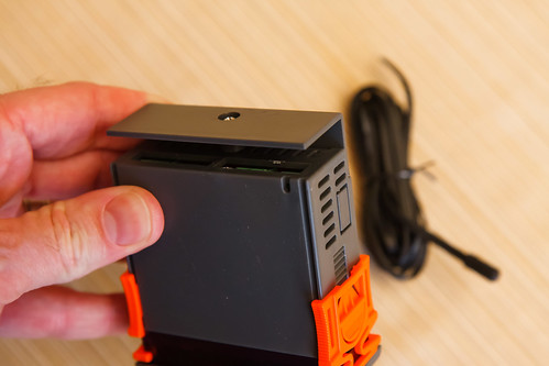
You press at the center to slide each clamp off the end. Now put the controller in place from outside the box. Then slide the orange clamps into place to tighten the unit onto the plastic project box. The screw at the end removes a shield that protects the wire connections. I didn’t feel this was needed and removed it.
Step Eight: Mount the Electrical outlet into the project box. After I was sure it fit in the hole I cut, I set it in place and drilled two small holes on either end and secured the outlet with a small screw and bolt on each end. You can now install your plate using the supplied screw into the center of the outlet.
Note: It may be easier to perform all the wiring by leaving the controller and outlet free and installing them after the wiring is done. Just be aware and get them generally in position (inside the box) so the wires don’t end up connected outside the project box with you unable to install.
Step Nine: At this point you are ready to start connecting wires.
How to Connect Wiring to your Temperature Controller:
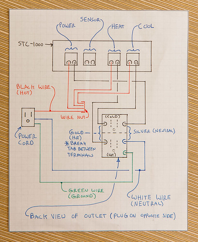
I have made this simple wiring diagram to try and show how things are connected. (.pdf version)
As good as a picture or diagram can be, It is helpful to get a description of what is happening, so I will go through all the connections. If you are unsure, use the diagram on the STC-1000 as a guide for what connections are what.
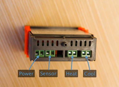
When you look at the STC-1000 from the back, there 4 pairs of wire terminals. Going from left to right, the pairs are:
- 1st: Power
- 2nd: Temperature Probe
- 3rd: Heat
- 4th: Cool
The terminals on the STC-1000 come closed. Crank them counterclockwise with a small flathead screwdriver to open and to allow you to insert the bare wire end. Tighten gently; enough to make a secure connection but not so much to strip the small screws.
Looking at the back of the electrical outlet, you will see a screw at the corner by itself – this is the ground terminal. As I described previously, there are two screw terminals in silver that are ‘neutral’. On the opposite are two (now separate) gold terminals to serve the heating circuit and the cooling circuit. I’m going to refer to the ‘bottom’ of the outlet as the side closest to the ground terminal and the ‘top’ as furthest away from the ground terminal.
The power cord has three wires: white (neutral), black (hot), and green (ground). So, let’s start with the green wire from the power cord. Connect this to the ground (corner) terminal at the back of the outlet.
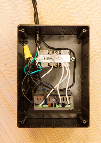
Next, let’s take care of what I call the ‘hot’ connections. Take three separate pieces of your 8″ wire and connect them to the left (of two) terminals in the STC-1000 for: Power, Heat, and Cool. Then, take the end of those three wires and twist together with the black ‘hot’ wire from the power cord. So, that is four wires being twisted together and connected – use your screw-on wire cap. I added a little electrical tape below this to hold the wires together.
Next, take three other pieces of your 8″ wire and connect them to the remaining ‘right’ terminals for power, heat, and cool. Connect the ‘power’ wire from the STC-1000 to the lower silver (neutral) terminal on the electrical outlet. Connect the ‘heat’ wire from the STC-1000 to the upper gold terminal on the outlet and the ‘cool’ wire to the lower gold terminal.
The only remaining wires to connect are the two leads from the temperature sensor to the sensor terminals at the STC-1000. It makes no difference which wire goes in what terminal. The temperature probe wiring was longer than I needed. I bundled the extra with a zip tie and stored inside the project box.
This wiring scheme has the upper outlet as heat and the lower outlet as cooling. After you have tested for operation, it would be a good idea to label the outlet cover for ‘heat’ and ‘cool’ near the respective outlets.
Final Steps and Programming the STC-1000:
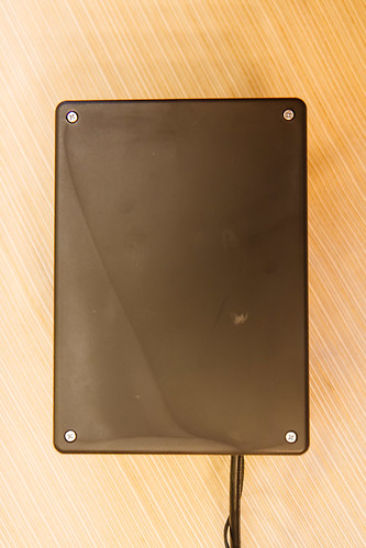
Step Ten: Put the cover on the back of the box and secure with the included screws.
That’s it. If I can do it, anyone can! From here, you need to plug the controller in and connect your heat / cool devices as applicable. I am only using this to control my Hydor aquarium heater, so there is only one plug connected to the outlet and it is on the ‘heat’ outlet. I don’t have anything in the ‘cool’ outlet but expect I will be wiring up some fans in the future.
One downside to this unit, for Americans, is that the controller uses Celsius instead of Fahrenheit. It’s not that big of a problem and is just something to work with. I made a conversion table to print and tape onto the box. That lets me quickly confirm what I am doing and seeing.
EDIT: There is now available a version of this temperature controller that lets you choose between Celsius and Fahrenheit: Inkbird All Purpose Digital Temperature Controller.
Instructions for programming the controller are included in the box (here is a .pdf of the instruction manual). It’s not the easiest to setup, but nothing that can’t be accomplished by reading carefully. There are four parameters that you can program:
- Function 1: Temperature Setpoint. This is easy to understand; the temperature you want to maintain. This can be set from -50°C to 99°C (-58°F to 210°F).
- Function 2: Deadband. The deadband is a range of temperatures where you will not have cooling or heating. This keeps the equipment from ‘short cycling’ and ensures you don’t have simultaneous cooling and heating. This value can range from 0.3°C to 10°C. Let’s say you have your controller set at 25°C (Function 1) and your deadband set at 0.5°C (Function 2). If the temperature is measured at 25°C then the unit does nothing. If the temperature falls to 24.5 or below, then heating is enabled. Conversely, if the temperature rises to 25.5 or above, then cooling is enabled. I have my unit set for the quickest response of 0.3°C. If you have equipment, either heating or cooling, that is oversized, you may want to increase the deadband if you observe the temperature overshooting beyond the set point.
- Function 3: Compressor Delay Time. This applies only to cooling mode and can be programmed from 1 to 10 minutes. If the cooling circuit goes from powered on to off, this function sets the time delay before cooling mode can start again. This is meant to save wear and tear on the compressors in DX refrigerant equipment.
- Function 4: Calibration. This can be set from -10°C to +10°C in 0.1°C increments. The default is 0. If you wanted to take the time to check the calibration of your temperature probe, you could find the offset and program the correction into this function. For instance, If you put the probe in an ice bath you trust is 0°C but the controller reads -0.5°C, you would enter a value of +0.5°C into Function 4.
In operation, the LED display shows the temperature at the sensor. There are two LED indicators that show if the unit is in cooling mode or heating mode. If neither is illuminated, the temperature set point is satisfied and it is not cooling or heating.
The STC-1000 has built in memory so that when you loose power to the unit, it retains your programmed settings after power is restored. This written memory is some sort of flash memory that does not need power, which is to say it does not rely on a coin type battery for the memory.
Use in Your Aquarium:
For the controller to function correctly, you need to place the sensor where it can accurately report the temperature of the display tank. Avoid placing it near the heater or near the water supply outlet. The best place to put the sensor is near or in the return out of the display tank.
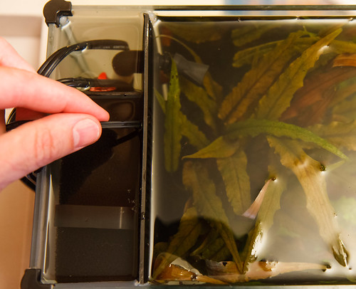
In a Fluval Spec aquarium, there is a very convenient place to put the sensor. I routed the sensor wire into the aquarium at the opening where the pump cord enters. I then route the wire across the filter section, across the top of the filter sponge, and push the sensor down next to the filter sponge and the inside wall. I push it down a few inches to ensure it is getting a good reading of the water.
This location allows return water leaving the display to flow over the sensor. It provides a good indication of the tank temperature without being affected directly by the heater output.
Since the controller is responsible for on/off of the heater, the only thing the heater needs to do is heat whenever the power cord receives power. Set the thermostat of your aquarium heater higher than your desired set point. My controller is set to around 78°F but I set the temperature on the Hydor heater to 90°F to ensure it is on when heating is called for. I don’t have worry about the temperature being set so high because the controller will kill the power when the setpoint is reached.
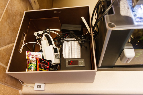
Once you have it set, there is not much need to fiddle with it. I have the controller sitting in my storage box. Every so often I peek in to check the temperature. So far, the setup has been very reliable – maintaining perfect temperature in the colder months. I hope to install a small fan someday soon to help alleviate the temperature rise in the summertime.
Update – Alternative to the DIY Temperature Controller:
Since I made my do it yourself temperature controller, I have discovered that there is now a ready-made product for those that don’t want to build the temperature controller. Check out my preview and my full review of the Inkbird ITC-308.



Great tutorial. The step-by-step instructions with the photos and your wiring diagram explain this perfectly. This is something I am going to look into making.
Thanks!
Thanks! It’s confusing at first glance, but I thought the diagrams help to explain. Go for it – if I can built it, anyone can!
Great idea! I was looking for something to turn off my water heater in case it failed. Using your idea what I’m going to do is tie it into the cold contacts of the stc-1000 so in case of a rise of temperature at a specific set point it will shut off my water heater. I was looking for redundancy instead of a substitute to the built in thermostat on the heater. Thanks alot! Good job with the step by step instructions!
Simply an excellent instructional guide! You have saved me so much work I owe you my first born 🙂 Thanks so much!
Great write-up, really amazing detail. Helped me assemble my controller so thank you!
One thing to note about the ITC-1000: when set in Fahrenheit mode, the smallest increment you can set the deadband for is 1 degree F. When in Celsius mode, you can go as low as 0.3. What this means (if I’m not mistaken) is that in Celsius mode, you have a higher degree of precision with which to control your heater.
You are very welcome – glad it came together for you!
Very interesting note about the Fahrenheit operation of the ITC-1000. Strange. Yes, it would appear that it is not as tight in control if it really allows no more than a 1 degree deadband. Thanks for bringing that up. Seems like it might be a programming mistake.
There’s not really much difference between the two precisions. A temperature difference of 1°F is the equivalent of a temperature difference 0.556°C. This is because the range of temperatures between freezing and boiling at F is 180 and that of C is 100. Either of the two (F and C) give you pretty close to the same precision of measurement.
This looks awesome, Nate. Nice work! Curious as to how it’s still working for you since it’s been about a year and a half since you posted this. I can’t quite bring myself to spend the money on a brand name controller so I’m trying to do as much DIY automation as I can. thanks!
It is still working great. Temperature is rock solid year round. I think it helps keep the fish healthy by eliminating the fluctuations.
As the primary purpose of this unit is protection in case of a thermostat failure on the heater, it seems foolish to set the heater high and rely on the STC. All that does is move the risk to the STC failing. Surely it makes sense to have the temperature set on the heater, with the STC providing a second level of protection IF the heater foes wrong.
I appreciate your trying to think this through. You are right; it does now rely on the STC; however, the mode of failure of the STC will most likely be ‘power off’. I can’t see any scenario where the controller will fail and still energize the heater.
At any rate, it’s not just about safety, but utilizing the increased accuracy of the controller. For the controller to be able to do its job, you need to set the aquarium heater thermostat higher than the desired setpoint to get it out of the way.
I run dual heaters in some of my setups, is there a way to wire this so that both outlets work for heating?
Hmmm, not sure what you mean. Couldn’t you just multiply the single heating outlet to two outlets with some sort of extension cord of sorts?
Well, I’d like to make up some excuse about preferring not to piggy back Extension cords off something plugged into a surge protector or something like that but the fact is I simply didn’t even think about something as simple as a 2 way outlet splitter.
Thanks for the quick reply. I look forward to putting some of your mods to use.
BC, don’t do this…
Step Six: Prepare the electrical outlet for dual control.
Put in a second duplex electrical outlet and wire it to the cooling circuit.
I included a third duplex electric outlet which is always hot to run my pump and/or other items you always want powered on.
As a quick note! My reef tank is rock solid especially during the latest heatwave I was almost in a panic as outside temps soared above 30*C; I was constantly watching my temp on the STC-1000. Absolutely perfection as the temp fluctuated to 25.5*C click, on came the fans as the tank reached its operating temp of 25*C click fans off, fish smiling all round… I bought the STC after much research and came to the conclusion… Why would so many ardent beer drinker risk their growths on rubbish or inferior product! Give your fish a near risk free ( power outages not withstanding ) life and buy the STC-1000 and help to keep your heart healthy.
I think this is amazing and genius! I was wondering if you had perhaps a YouTube video or would ever consider doing one for these?? Im always wondering if I’m off and would love to see the whole process if you have any links to tutorial videos ! This is great thanks for sharing!!!
Very interesting, STC-1000 it’s on the way.